



An architect or surveyor receives a 3D point cloud following a laser scan and is unsure how to proceed – in what format to send it, to whom, and for what purpose. This raw data accurately measures an actual condition. It is neither a plan nor a ready-to-use model. Its value depends on what is subsequently extracted from it.
What a point cloud contains
A point cloud comprises several million points, each defined by three coordinates – X, Y and Z – within a given coordinate system. The scanner also records, for each point, an intensity value (the energy of the reflected laser signal) and, often, an RGB colour value captured by an integrated or associated camera.
The density of points varies depending on the distance between the scanner and the target surface, and on the resolution selected on the device before each station. A nearby wall scanned at high resolution produces a dense mesh. A distant façade, scanned at low resolution, results in sparser areas.
Georeferencing determines the traceability of the entire dataset. This involves linking the point cloud to a recognised coordinate system, or to topographical targets measured using a total station (the instrument used to measure angles and distances in surveying), so that each point retains its meaning outside the acquisition software.
Without this linking, the point cloud remains consistent within its own reference frame. A local alignment, based on a common point identified in both the point cloud and the plans, then allows for a direct comparison – less traceable than a full georeferencing but sufficient for spot checks.
From the laser station to the usable file
Data acquisition is carried out using a static laser scanner, mounted on a tripod and moved from station to station, or using a mobile scanner carried by hand or mounted on a trolley to quickly cover large areas. Each station captures a complete 360-degree scan around its point. Registration then aligns these stations with one another, either by recognising common features or using physical targets positioned within the scene.
The raw or semi-processed result is generally delivered in one of these formats. The E57 format, standardised by ASTM E2807, serves as a neutral exchange format between software programmes. It retains the coordinates, intensity, colour and station metadata. The RCP format is part of the Autodesk ecosystem and allows the point cloud to be processed directly in ReCap before being imported into Revit. The LAS format, maintained by the ASPRS (American Society for Photogrammetry and Remote Sensing), remains the benchmark for geospatial LiDAR data, particularly that derived from mobile or aerial surveys.
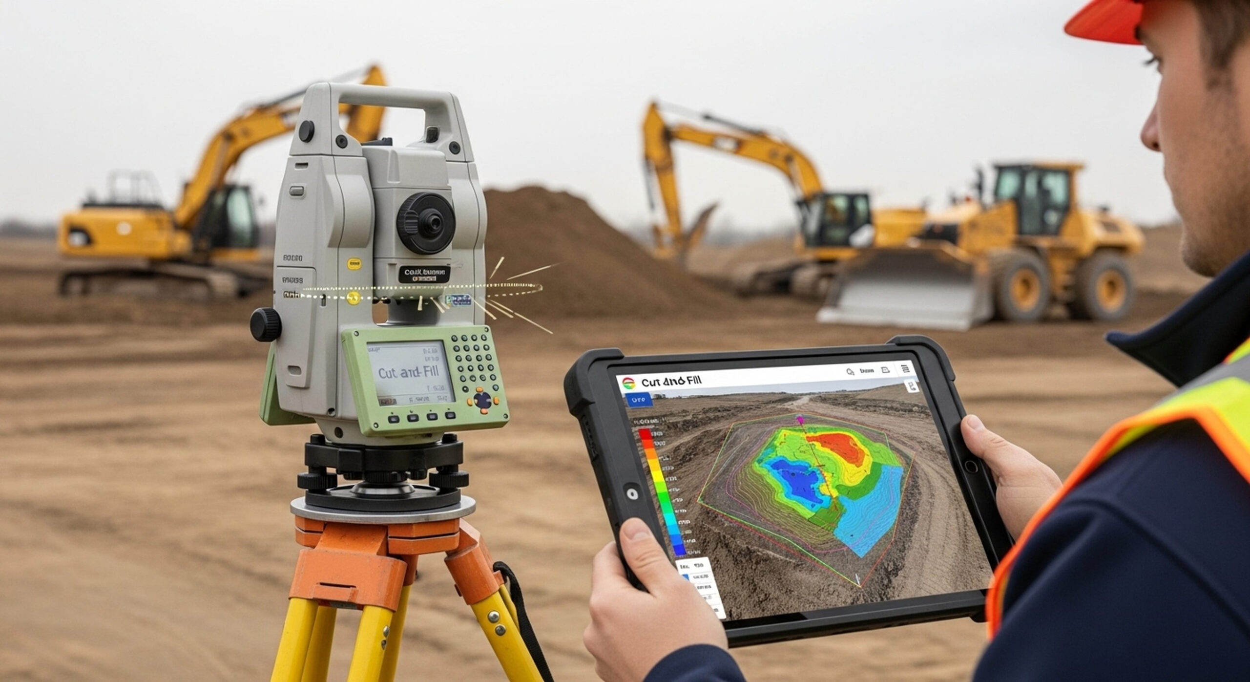
The total file size depends on the number of stations, the chosen resolution, the presence of RGB colour, the export format and the compression level. This volume of data is difficult to handle without software specifically designed for this type of file.
The intended use dictates the level of detail
The same survey can serve very different purposes depending on whether it is used for a one-off inspection or a full design project.
Dimensional checks on a completed structure, verifying the plumbness of a load-bearing wall, or comparing the as-built condition with the original plans all stem from the same survey, but do not require the same processing. A surveyor can work directly within the cloud, taking measurements or specific cross-sections without having to carry out a full modelling process.
An architect, by contrast, requires a structured deliverable. A 2D plan readable in DWG format or a BIM model – the digital model structured by elements (walls, slabs, openings) resulting from the Building Information Modelling process – integrates more easily into their own design process.
Without prior scoping – including defining the area to be covered, the target tolerance and the delivery deadline – the point cloud remains a mass of data that is costly to analyse. The processing time, and therefore the cost, depends directly on this initial scoping.
Separate deliverables for each discipline
Conversion into a BIM model involves manual or semi-automated modelling, element by element. Some tools automatically extract flat surfaces or simple geometric shapes from the point cloud, but a reliable model requires human validation and correction before delivery. This work accounts for the time and cost associated with processing, which are separate from those of on-site data acquisition.
Three types of deliverables are most common: DWG drawings, a BIM model with a contractually defined LOD, or a dimensional control report with quantified discrepancies. The LOD (Level of Development) describes, according to the BIMForum convention, the degree of reliability and development of a model element, not merely the level of detail in the survey. Their uses, formats and the software required to view them differ significantly, as summarised below.
| Deliverable | Typical use | Format | Viewing software |
|---|---|---|---|
| Raw point cloud | Point-by-point inspection, direct dimensioning | E57, LAS, RCP | CloudCompare for E57 and LAS, ReCap and Autodesk applications for RCP |
| DWG drawings | Site coordination, set of drawings for a planning application in accordance with the relevant authority’s requirements | DWG | AutoCAD |
| BIM model LOD 300 | Design basis, with the geometry of elements defined in terms of size, shape and position. MEP (heating, ventilation, plumbing and electrical) coordination is covered by LOD 350 | RVT, PLN | Revit, Archicad |

Factors determining accuracy
The reliability of a survey depends on a combination of several factors, never on a single figure. The equipment used, the range and the field of view determine a margin of error specific to each scanner. The calibration protocol between stations, the number of re-alignment targets and their spatial distribution directly influence the consistency of the final point cloud.
Site conditions are just as important. A dark room primarily limits the quality of the RGB texture captured by the built-in camera, without affecting the laser measurement itself. Reflective surfaces, such as glass or polished metal, and grazing angles, on the other hand, degrade the laser signal and generate noise or gaps in the point cloud.
The accuracy specified by the scanner manufacturer, usually expressed in millimetres at a given range, can only be achieved in the field through a rigorous calibration protocol. The number of registration targets and their spatial distribution, as well as the actual range of the survey, mean that results from the same device can vary from one site to another.
The raw data in itself guarantees nothing. It is the data acquisition protocol and the subsequent quality control that make the point cloud traceable and usable for a given purpose.
Key considerations before commencing a survey
A one-off compliance check is based directly on the raw point cloud or on a report of quantified deviations, without any intermediate modelling. A design or technical coordination project, by contrast, requires a BIM model structured by elements, with a Level of Detail (LOD) specified in the contract.
The delivery format and the chosen LOD must be agreed with the service provider before the on-site work commences, not after the point cloud has been received.