



What holds back a poorly structured project
A Scan-to-BIM project links the laser survey to the digital model created within a BIM (Building Information Modelling) environment. It rarely fails due to a lack of data, but rather when the intended uses of the model have not been defined prior to the survey. This scoping takes precedence over any considerations regarding hardware or software.
The principle underpinning the entire production chain
Three concepts underpin the scoping of a Scan-to-BIM project and are often mistakenly confused: measurement accuracy, LOD and LOI.
Measurement accuracy refers to the tolerance of the point cloud, expressed in millimetres. LOD (Level of Detail) describes the geometric accuracy of a modelled element. LOI (Level of Information) relates to the data associated with that element, such as material, dimensions and product references.
A dense point cloud does not compensate for imprecise specifications, nor does it justify modelling areas of no significance in detail, as this lengthens lead times without improving project decisions.
Prepare the survey before going to site
An effective survey requires preparation before arriving on site. Access to the premises, the presence of a guide to open up technical areas or attics, and the identification of areas obscured by furniture, scaffolding or vegetation all determine the number of survey points required and the quality of the final alignment.
The stationing strategy aims to minimise blind spots – areas not visible from any station – whilst keeping the time spent on site to a minimum. Registration targets – spheres or checkerboards positioned within the field of view of several stations – facilitate the alignment of the point cloud when the building’s geometry alone is insufficient.
Each station is recorded with its position, orientation and date of capture before being integrated into the overall point cloud. This record enables the source of any discrepancy to be traced if a subsequent check detects one.
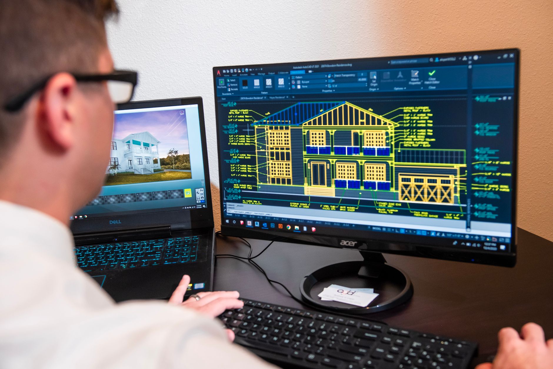
Laser surveying and point cloud capture
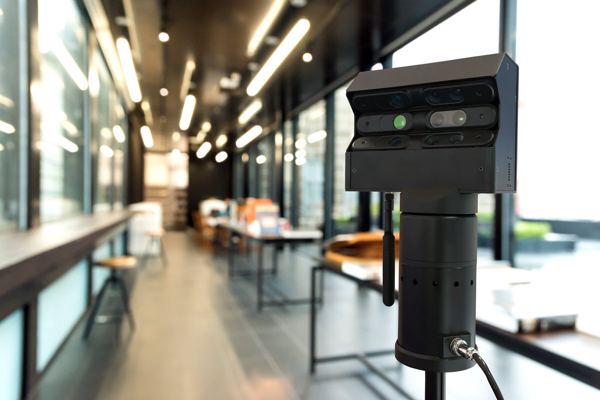
The survey is carried out using a terrestrial laser scanner, positioned at several successive stations—commonly referred to as ‘setups’—spread throughout the building. Each station captures a local point cloud.
This point cloud is then registered—that is, aligned with neighbouring stations within a common reference frame—to form a single, coherent point cloud covering the entire building. This operation determines the entire subsequent workflow.
The coordinate system must be selected prior to the survey: either a local reference system specific to the building or a georeferenced system linked to the official cadastral survey. This choice determines coordination with engineering firms specialising in structural engineering and MVS (heating, ventilation, sanitation and electricity), which often work within a reference system common to the project.
The measurement tolerance depends on the scanner model and the line-of-sight distance. For a device such as the Leica RTC360, which uses LIDAR technology to capture up to two million points per second, the manufacturer specifies a range accuracy of 1.0 mm plus 10 ppm (i.e. 10 millionths of the measured distance), corresponding to a 3D point accuracy of 2.9 mm at 20 metres.
Depending on the terms of the contract, the registered point cloud may itself constitute a deliverable, generally supplied in E57 or RCP formats prior to any modelling.
Areas to be surveyed and proportionality of the project
A proportionate approach tailors requirements by area, by object and by phase, rather than applying a uniform Level of Detail (LOD) to the entire building. This prioritisation remains the most direct means of controlling the cost of a project.
The level of detail depends on the intended use, not the element category. A façade requiring renovation, where the geometry determines the project’s feasibility, warrants a high LOD, often between 300 and 350, supplemented by an LOI which documents the material or product reference only if a construction decision depends on it. The LOI is therefore set independently of the LOD, on a project-by-project basis. Attics, secondary plant rooms or any areas not requiring conversion may, on the other hand, remain at LOD 200, with a minimum level of information.
Feasibility studies, which are exploratory by nature, sometimes require a degree of flexibility and justify a deliberately low LOD for non-priority areas, even if this means refining it later as the project progresses.
Modelling and level of detail (LOD or LOI)
Modelling converts the point cloud into parametric BIM objects – walls, slabs, ductwork, joinery – each of which carries geometry and, depending on the target LOI, associated data.
At LOD 200, a wall is represented by an approximate thickness and a general position, which is sufficient for a site plan or a feasibility study. At LOD 300, the same wall includes its actual measured thickness, its exact position and any openings.
At LOD 350, a service duct also includes its connection points, which are useful for coordination with other trades prior to construction. This level is primarily used to detect clashes between service networks.
Modelling is carried out in Revit or Archicad, depending on the software used by the recipient design office. The native format remains necessary at this stage to preserve parametric families and associated data; a neutral exchange format is typically used further down the workflow.
The measurement accuracy of the survey, in millimetres, and the modelling tolerance – the accepted deviation between the modelled geometry and the source point cloud – remain two distinct concepts. A point cloud accurate to ±3 mm can be modelled with a wider tolerance if the project’s requirements do not demand greater precision.
Quality control and acceptance criteria prior to delivery
Prior to delivery, the model is compared with the source point cloud, element by element or zone by zone, to verify that the deviation remains within the modelling tolerance set beforehand. If the deviation exceeds this threshold, the element in question is reworked before validation rather than simply flagged.
The check also verifies that the coordinate system applied to the model corresponds to the reference frame validated at an earlier stage, using a sample of elements representative of each area. Consistency between trade disciplines, structure, CVSE and architecture is verified at this stage rather than after transmission to the engineering firms.
The tolerance thresholds below are indicative and should be adjusted according to the practices contractually agreed for each area, as the LOD alone is not sufficient to determine a modelling tolerance.
| LOD | Typical modelling tolerance |
|---|---|
| LOD 200 | ±15 to ±20 mm |
| LOD 300 | ±5 to ±10 mm |
| LOD 350 | ±3 to ±5 mm |
This check determines the reliability of decisions made on the model. It does not guarantee absolute accuracy for every element of the building, only compliance with the thresholds set for each zone.
Expected deliverables at the end of the project
The Scan to BIM project concludes with several distinct deliverables, each serving a different purpose within the project.
- Registered point cloud, for verification or subsequent revision
- BIM model (RVT or Archicad file), for coordination between trades
- IFC file, a vendor-neutral, interoperable exchange format, for practices not using Revit
- Existing building plans (DWG), for planning consent or construction
The format required by the authorities varies depending on the local authority and the procedure; this should be checked with the relevant authority before finalising the contract. In practice, plans submitted for public consultation are frequently expected to be in DWG format, whilst IFC files are mainly exchanged between engineering firms using different software.
Keeping the model up to date after handover
The Scan-to-BIM model does not end with the handover of the files. Any subsequent alterations to the building – such as a moved partition wall or an added service duct – should be incorporated into the model so that it remains a reliable reference for technical management.
Without updates, the original point cloud quickly reverts to being the only accurate source of information on the actual building, which renders the model useless for future decision-making. This updating is generally the responsibility of the technical department that manages the building on a day-to-day basis, rather than the contractor who carried out the initial survey.
Defining the scope of the project before starting the survey
Scoping checklist
- Intended BIM uses (HVAC coordination, planning application, technical management)
- Priority areas and areas where a summary level of detail is sufficient
- Coordinate system selected for the entire project
- Target LOD and LOI, zone by zone
- Procedures for checking the model prior to handover
These points should be discussed with the client, the architect or the main contractor before arranging any on-site meetings.
Key points to bear in mind before launching a Scan-to-BIM project
These criteria should be set out in writing in the contract, not merely discussed verbally, to avoid any subsequent disagreement regarding the exact scope of the work.
AB 3D Scanning draws up a quotation based on BIM requirements and the expected deliverables, as specified in advance with the design consultancy or architect.